In May 2021, I finished my Master's degree in Mechanical Engineering at CWRU. This article is about the project I did my thesis on and will gloss over many details. To learn more, check out my defense or thesis. This is one of my favorite projects of all time because I got to put together lots different concepts for the project, and I got to see this very long project through from start to finish.
This is a model of the final product I came up with - it's a power unit for a lower extremity exoskeleton that is used as a mobility aid.

The first photo below shows the exoskeleton this power unit would eventually get installed on. It is developed by researchers CWRU and VA. You can read more it here. Also, check out the bibliography in my thesis for further information.
A "power unit" in this case is a unit made up of a motor, position and torque sensors, gearbox, and an optional safety brake. The power unit drives joints in an exoskeleton that is used to assist muscle-first motion in users, who are patients with varying degrees of spinal cord injuries.
The last three images below show the previously designed actuators. They were each built to test a specific concept or design idea. I was given a task to make the next version with the lessons learned from the previous generation power units.


I started my design by picking the components to satisfy the torque and speed requirements of the power unit's output side. I compaared about a dozen brushless motors before I could pick one, then looked at alternative gear layouts before I decided on a mix of planetary and inline gears to get to the torque needed.
A small footprint, light weight, and high mechanical efficiency were the most important criteria for this gearbox, and this is the criteria that drove my decision making at each step.
The images below show (left to right):
1. The final arrangement of the power transmission components: The motor, two stages of inline helical gears, a final stage of planetary gears, then finally the torque sensor on the output side
2. Just the gears in the system
3. Layout of the planetary gearset
4. FEA showing effects of weight reduction on the large helical gears


For this very compact design to work, I needed to make my own bushing and hide the torque sensor inside it to isolate the sensor from any sideways forces. This is necessary so that the sensor is influenced only by the output torque and not other forces on the output side.
The top image below shows the layout of the main bushing and the components around it that make up the output side.
The three images below show (left to right):
1. Layout of bearings and bearing plates in the final assembly
2. Covers and main housing that locates all the assembly components
3. FEA verifying that the lightweight housing is stiff enough to survive the maximum torque output of the power unit


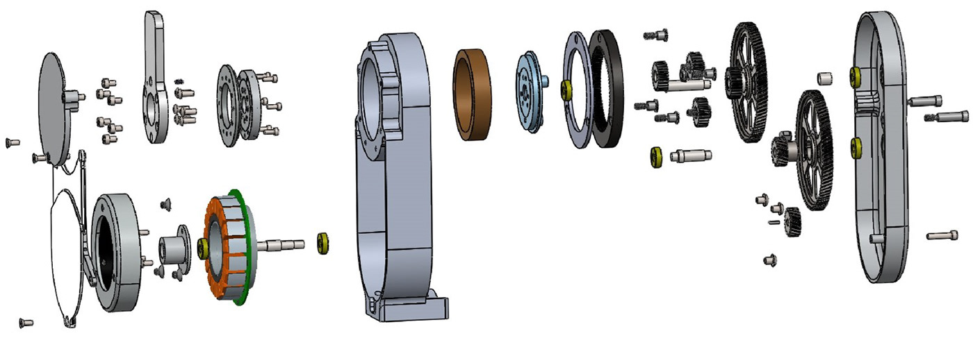
The exploded view below shows the placement of all 85 components of this power unit.
Finally, the first look at the finished assembly with a stubby output arm for testing purposes.

After the build, it was time to test the power unit to ensure the power unit performs as expected. My thesis goes into much more detail about the data analysis, but in short, the power unit met or exceeded all expectations.
The figures below show (left to right):
1. The setup used for testing - A Biodex torque testing machine
2. Isometric torque as measured by the Biodex
3. A no load test of the power unit that helps measure the friction and stiction in the system
4. Overall mechanical efficiency of the power unit at various rotational speeds


Lastly, these images show the different power unit designs and how the size and form factor of the unit changed over time.


